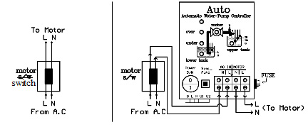
| This system not only saves manual labour but also prolong life of motor thanks to the programme employed to control the motor of water pump automatically. The system consists of; |
| 1. Automatic cutting out of power at the minimum and maximum voltage 160 and 240 respectively. |
| 2. Prevention of motor from running if there is no water in the sources of water such as underground pipe and tanks. |
| 3. Automatic cutting out of power if water does not come out from the outlet pipe in three minutes for some reson. (For example; the motor does not work well or there is no water in the pipe.) The motor continues to run if water comes out of the outlet pipe. |
| 4. If water does not come out from the outlet pipe, the motor automatically stops running and restarts in 30 minutes and continues to run for three minutes waiting for water to come out. (These steps take place every half an hour.) |
| 5. The electronic sensor stops the motor automatically when water level reaches the full mark.
|
| 6. The motor starts automatically when water level reaches the empty mark. All these functions are invented with the use of electronic sensors to ensure safety. |
| Installation |
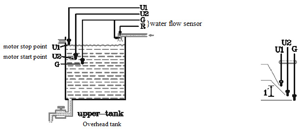
| Sensor U1 |
= Install it at the highest water level mark desired. The pump motor stops when water touches the mark (U1). |
| Sensor U2 |
= Install it at the lowest water level mark desired. The motor automatically starts as soon as water level lower under the mark (U2). (For example; if you want to have the motor started when the water level lower by 5 inches, install U2 at five inches from the brim (edge).) |
| Sensor G |
= Install it at 1 inch below U2. |
| Senor G&R |
= Install them in the mouth of the outlet pipe. They stop motor from running if water does not come out in three miuntes or continue to run if water comes out. In case of no water coming out, the sensors stop the motor and restart it in 30 minutes. |
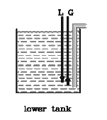
| Sensor G&L |
= They are installed in order to know whether or not there is water in the underground tank or in YCDC Pipeline. Sensor G should be installed at the lowest water level desired in the underground tank. Pump motor runs as long as the senor touches the water but it stops as soon as water level lowers than the sensor. Install sensor L 1 inch above the sensor G. If the source of water is the YCDC pipeline, it is impossible to install the sensor in the pipe. In this case, connect G and L with a wire on the connector of the controller. This enable all other functions to work properly. |
| Semi-Auto ( S/W ) |
= Press the switch once and release it when emergency pumping is needed. The motor starts in a moment after pressing the switch and it stops automatically when water level reaches the full mark. |
| Note |
If automatic contorl system does not work properly, the sensors installed in water need cleaning with the use of a brush so that moss and dirt are removed. (It is recommended that senosors should be cleaned once a month.) |